Project History
With a father in the RAF Bomber Command in WW11 and a grandfather in the RFC in WW1 I grew up with tales of aviation exploits in both wars.
A trip over to my father’s old ATC hut in Guidford and a glimpse of a “Link Trainer” at the age of 5 was enough to cement the start of a lifetimes interest in aviation,
I wanted to sit inside it but was unable to and had to wait 60 years for that experience until I purchased one myself after years of searching for one that was for sale.
After flying model RC aircraft I progressed to obtaining a PPL and bought and flew a 1940’s tailwheel aircraft. Wartime aircraft always had me fascinated and I wondered what it was like to fly a Lancaster Bomber, at night, on a wartime mission.
I quickly realized that the only way to experience this was to build a full-size wartime simulator using as many WW11 original parts as possible.
What followed was a project of 20 years and about 10,000 hours to build a working Lancaster simulator.
Via the internet and ebay I scoured the world to secure as many original parts as possible. Tracked down information required to set out and make the metal parts to original AVRO dimensions.
Obtained and studied original manuals to learn what every part looked like and how it worked, made many trips out to museums and private collectors to gain the detailed information required to make the various items and structures.
Once I had obtained all this knowledge I had to work with a friend to design and make all the computer operated gauges we needed to look and operate as the real ones did.
Finally to team up with a colleague who was able to obtain the software to make everything communicate with the computer, both flight commands in and gauge information out.
What follows is a very brief description of the work involved with some illustrations.
One of the first items to draw, which took 3 months, was the main instrument panel. All instruments had to be obtained first and to locate an original AVRO drawing. Original drawings were in very poor condition and a lot of work had to be done to fathom out the dimensions which were barely readable in most cases. Once drawn, the hard way, by hand, it was put into Autocad and the first one cut out on a water jet cutter.
The floor then had to be set out accurately so that the formers would be positioned correctly on the sides and all rivet lines would be as per the original. To get this information a set of cd’s were purchased with 22,000 scanned drawings and a visit to photograph and check inside an actual Lancaster Bomber aircraft.
The pilot’s floor could then be made and formers fitted to the cross members. Once done the stringers could be fixed in place and the sheeting cut and riveted in place with a cockpit rail formed to fit along the top to eventually take the canopy. Also in the picture are the cast stops which had to be made and fitted in the correct position.
The outer skin was riveted as per the original with imperial spacings and multiple aluminium sheets. Due to workshop space limitations, although the fuselage was ultimately to be built from former 6 through to former E. it had to be built in two separate sections then joined with an invisible join when completed.
Many items had to be made from scratch, one of which was the trim tower. This was first constructed in Meccano, then wooden patterns made and sand cast in aluminium.
After which the gear arrangement, shown here, was incorporated into the finished article so that it operated exactly as the original trim tower would to enable us to fly the aircraft accurately.
One area that was hard to obtain was the rudder bar assembly. Shown here being restored and repaired by the late Jess Griffiths, a good friend and craftsman.
It is quite unusual in that I managed to obtain a double set so that both pilot and instructor were able to control the rudders on take off and landings which were both quite demanding.
The engineers panel had to be made by hand with all cutouts and associated bits fabricated.
This one has all original gauges, but later another one was produced with all computerized gauges that would work accurately with the flight simulator software.
An item like this alone was about 4 months work, with research and making of all associated parts. All work was undertaken outside of normal working hours.
Once the basic front section was completed, the canopy, a 1944 wartime dated example, had to be restored and fitted in place with all the various glazing and cover strips, some original some having to be made. The sliding windows had to be restored and cockpit rails made to enable the windows to operate as should.
It is at this point you discover if you have got all the measurements correct as if not it will not fit !
Once the canopy is in place the combing and other associated parts can be attached and it is then ready to be painted. Paint being mixed to exact colour as original, dark green and dark earth.
Once the outside complete the inside around the pilots area can be fitted out with restored seat, column, control spectacle and throttle box.
The port auxiliary panel can also be fitted along with all gauges made to operate with the computer software. The seat cushions and all trimmings were made to AVRO specifications in green leather as per the drawings. Rudder pedals now visible for pilots and flight engineer.
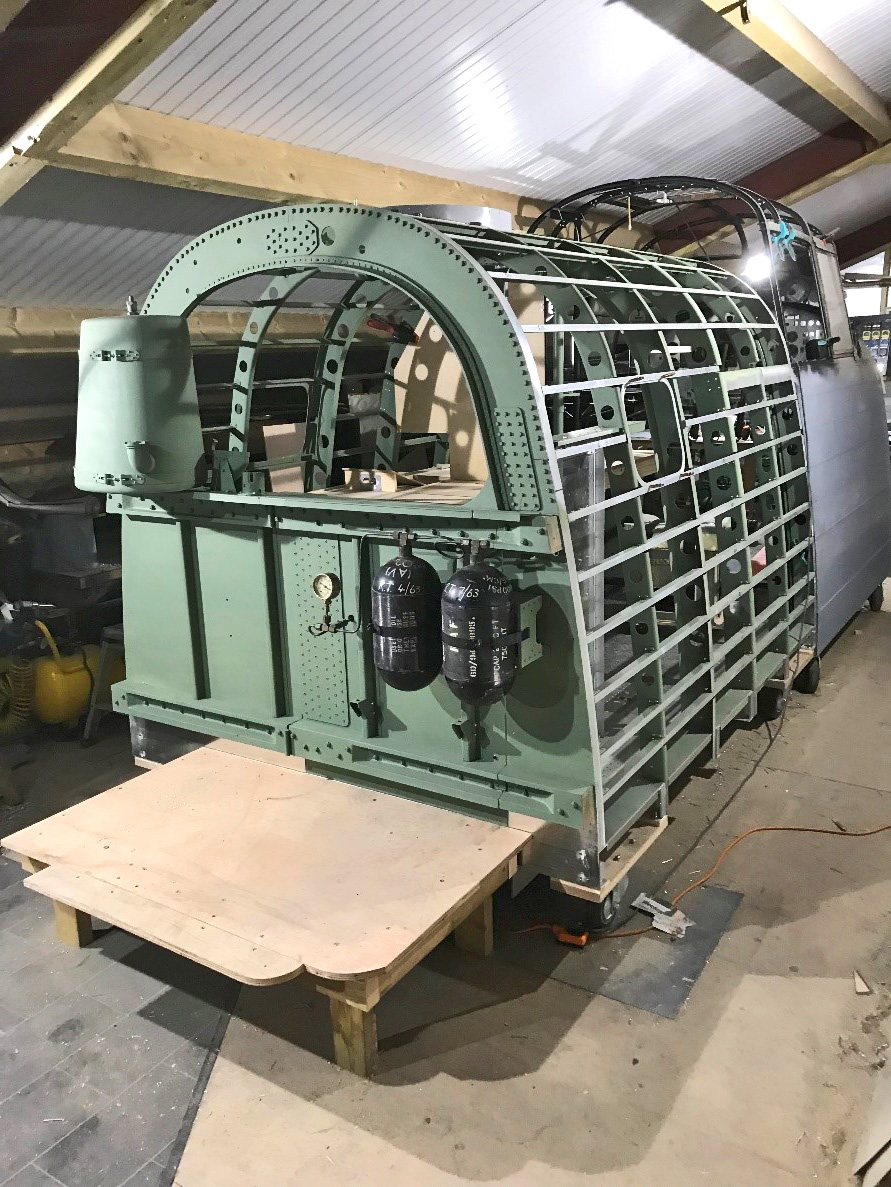
Now the rear section could be made, starting with former 6 which involved a lot of very accurate setting out and placement of castings to ensure all stringers would fit in exact place with an error of less than 1/16” (1.5mm).
Drawings researched for all riveted plates and exact positions for rivet and bolt holes.
The main part being cut out of one sheet of aluminimum to exact size by hand using a cordless jigsaw.
Some “cockpit green” paint applied at this stage as it would be awkward to get to some areas later.
All formers had to be hand formed and fitted in place attached to floor cross members,
Then stringers fixed into position and checked for accuracy.
The spacings had to be spot on and all marked out for drilling for rivets at the correct positions.
At this stage various other internal parts were fitted to ensure that no errors were present.
The items outside were the blowdown bottles for the undercarriage and the main hydraulic tank.
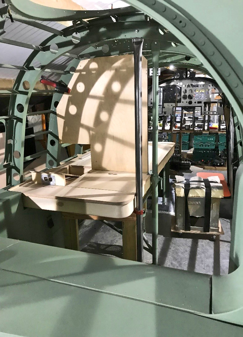
Inside can be seen some of the furniture being test fitted. It was very tight with no room for error.
Inside the fuselage initial fitting of the desk for both navigator and radio operator are test fitted before removal and painting.
The large vertical board is for the radio’s to be fitted with associated switches etc.
In this view you can see the section of the formers which had to be hand formed over a pattern and then lightening holes cut out.
At the top you can just see the hole for the astro dome which was fitted to allow star shot readings to be taken
The upright poles are part of the structure that allows the navigators seat to be fitted to allow it to swing to allow movement along the narrow starboard side.
Another view inside showing the H2S pole that carries the radar units and the navigators desk along with the panel for various pieces of equipment including a parachute pan for holding the parachute for the navigator which was attached separately to his harness if and when required.
The desk top lifts up to allow storage of charts inside and on top has a devise for plotting routes.
Under the table various black boxes are situated that power up the various bits of equipment, all valve powered requiring two separate voltages to operate.
Once all the structure is in place the equipment can be fitted exactly as should be.
Here the radio operators station with transmitter and receiver in place with “Fishpond” to the left hand side to detect enemy planes coming up behind.
Tucked in behind is the “J” switch which changes the aerials for the different frequencies used.
To the left is the intercom unit and oxygen supply.
Under the table are the power supplies and the seat is on the left hand side.
To the right is the main fuse box on the starboard side of the walk through.
The navigator position with seat positioned under the desk.
“GEE” situated left hand side of desk on movable rack and astrograph positioned high up to project star charts downwards.
Repeater compass in front along with anglepoise lamp and navigation computer.
The curtain is situated to his right hand side to enable the navigator to work away from distraction and bright searchlights shining up from below.
Just visible to the right is the H2S unit airborne radar.
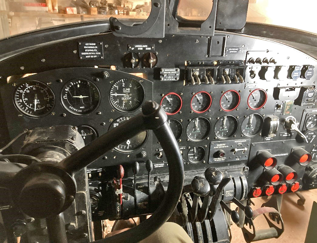
Almost ready for first flight ! All the gauges you can see are exact copies of originals but made to work with the computer software. Many of the switches are original and rewired to work in the simulator software.
All principle controls are connected to sliders that are routed through the interface before connecting to the computer.
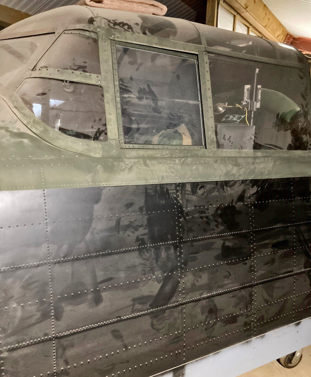
Below a slightly dusty but painted outside to correct colours.
To cover all the construction would require writing a book but I hope that this page has given some indication as to what was required to build an accurate Lancaster Bomber to wartime configuration using many original items.
Of note, the lecturer who originally taught me the skills to be able to work to this level of accuracy in metal was, James McQuaid, who himself was a wartime Lancaster flight engineer who was awarded the DFC after completing over 32 sorties.


